Redress Kits
Redress Kits
O-Rings and back-ups
Application
A variety of materials are available for use in O-Rings. The oil field industry has relied on 4 common materials. HNBR (Nitrile), Viton, Aflas, and FFKM (Chemraz, Kalraz, Perflas) are all common trade names for popular oil field elastomers.
Generally, as you move from HNBR to FFKM you gain chemical resistance and cost, but lose mechanical strength.
Features
- Hyrdrogenated Nitrile (HNBR. HSN) = Nitrile is a low-temperature performer with limited chemical resistance. Superior mechanical characteristics, particularly high strength helps reduce extrusion and wear. Do not use with ketones, esthers, strong acids, or chlorinated hydrocarbons.
- Fluorocarbon (FKM) Viton = Has an excellent resistance to high temperatures, ozone, oxygen, mineral oil, synthetic hydraulic fluids, fuels, aromatics and many organic solvents and chemicals. Low-temperature resistance is generally not favorable. Do not use with glycol, organic acids, or steam.
- Tetrafluoroethylene-Propylene (TFE) Aflas = This elastomer has an excellent chemical resistance across a wide range of aggressive media. Do not use with aromatics, ketones, or chlorides.
- Perfluoroelastomer (FFKM) Chemraz = Perfluroelastomer (FFKM) currently offers the highest operating temperature range, the most comprehensive chemical compatibility, and the lowest off-gassing and extractable levels of any rubber material.
The premature failure of an O-Ring can usually be attributed
to a combination of causes and not merely a single failure mode. It is
important to maximize sealing life and reliability by reducing the probability
of seal failure at the onset by the use proper compound selection, installation
and continued education of personnel.
 Abrasion
The seal or parts of the seal exhibit a flat surface
parallel to the direction or motion. Loose particles and scrapes may be found
on the seal surface. Rough sealing surfaces, excessive temperatures,
environments containing abrasive particles, or poor elastomer surface finish
may lead to an abrasion failure.
Use recommended gland surface finishes, consider internally
lubricated elastomers or eliminate abrasive components.
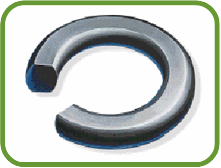
The seal exhibits a flat-sided cross-section, the flat sides
correspond to the mating seal surfaces. Excessive compression and temperature,
excessive volume swell in chemical, and specific elastomers with high
compression set lead to this failure mode.
Low compression set elastomers, proper gland design and material compatibility are all suggested solutions to a compression set failure mode.

The seal may exhibit
many signs of degradation including blisters, cracks, voids, or discoloration.
In some cases, the degradation is observable only by the measurement of physical
properties.
The selection of a more chemically resilient elastomer will prevent degradation.

The seal exhibits
blisters, pits, or pockets on its surface. Absorption of gas at high pressure
and the subsequent rapid decrease in pressure results is gas that was once
trapped inside the elastomer to explosively decompress and exit the seal. The
absorbed gas blisters and ruptures the surface as the pressure is rapidly
removed.
High modulus or a harder elastomer, as well as a slower decompression rate will prevent this mode of failure.
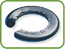
The seal develops ragged
edges (generally on the low-pressure side) which appear tattered. Excessive seal
clearances, excessive pressure, low modulus or hardness elastomers, or improper
sizing will lead to an extruded seal.
Decreasing gland clearances or use of a back-up ring will prevent extrusion.
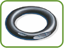 Installation Damage
The seal or parts of the seal may exhibit small cuts, nicks, or gashes. Sharp edges on the glands or components, improper sizing, or a low
modulus/hardness elastomer may lead to installation damage.
 Over-compression
The seal exhibits
parallel flat surfaces (corresponding to the contact areas) and may develop
circumferential splits within the flattened surface.
Gland design should take into account material responses to chemical and thermal environments.

The seal exhibits cuts or marks which spiral around its circumference. Difficult or tight installation clearances without proper lubrication may lead to this mode of failure. Excessive gland width is also a known cause.
Ensure adequate lubrication, or ensure the back-up ring is installed to reduce gland volume.
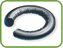
The seal may exhibit
radial cracks located on the highest temperature surfaces. In addition, certain
elastomers may exhibit softening, or a shiny surface as a result of excessive
temperatures.
Selection of an elastomer with improved thermal stability is a suggested solution.
Storage
The effective storage life of an O-Ring varies with the inherent resistance of each individual elastomer to normal conditions. The following conditions are suggested for maximum storage life:
- Ambient
temperature not exceeding 49ºC (120ºF)
- Exclusion
of air (oxygen)
- Exclusion
of contamination
- Exclusion
of light (particularly sunlight)
- Exclusion
of ozone-generating electrical devices
- Exclusion
of radiation
Generally, sealed polyethylene bags stored in larger cardboard containers ensure optimal storage life.
Removal
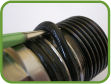
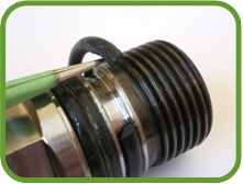
DataCan recommends that each O-Ring located on the electronics to batter barrel connection be replaced after every job. In order to maintain a reliable o-ring gland seal structure, the following procedure should be followed:
Using a soft O-Ring pick, lift the o-ring from the gland
Cut the O-Ring in half
When lifting the ring, be careful not to scratch the O-Ring gland.

Installation
DataCan recommends that each O-Ring located
on the electronics to battery barrel connection be replaced after every job. To
install an O-Ring without damaging the O-Ring or seal gland the following the procedure should be followed:
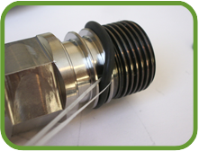
- Cut
a 1-2 foot length of wax string (dental floss)
- Place
the wax string through the O-Ring
- Use
the wax string to “walk” the O-Ring over the threads and into the O-Ring
glad
- Ensure
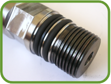
that the O-Ring is placed on the pressure side of the Back-Up
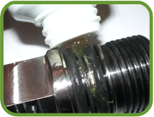
- Apply some O-Ring lubrication to the O-Rings. DataCan recommends using ParkerÒ O-Lube or Lubriplate L-461.

